
When prototyping a PCB, you need to think about the final stage of manufacturing your own board. But, how do you identify a chip with minimal marking on Pololu’s U3V40x family of regulators with minimal markings ?
(Spoiler alert : they use monolithicpower’s MP3437 step up converter)
Why was I looking for it ?
It happened to me recently when I was looking for a compact step up regulators for a university project. We were in need of producing a 6V-12V, high amp, momentary current for an electromagnet.
I stumbled on Pololu’s U3V40x family of step-up regulators. They were exactly what I was looking for but I also needed to know what their layout was to manufacture it later on our own PCB. However … the boards are not open source. Is it really that hard to find out what ic is used ?
The Search
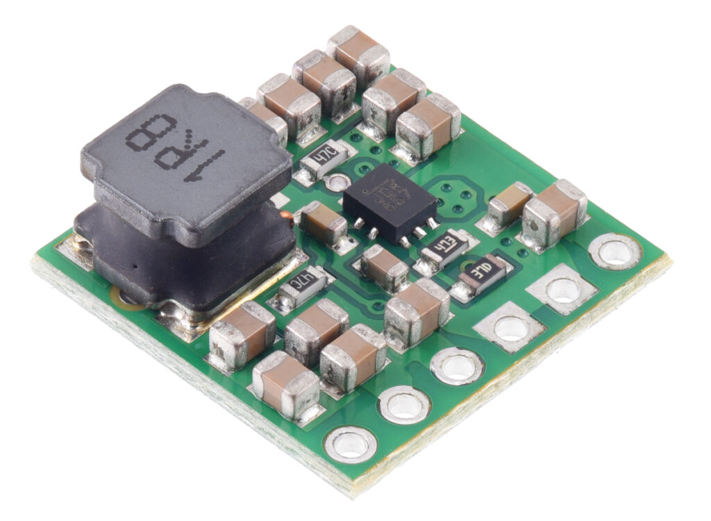
Well, what can we start with : we know from looking at the layout that there are a number of capacitors, resistors and an inductor (the later used directly for the conversion) and that the board is populated on one side only … but only one active ic remains. It is marked with “JDK 657”. It seems to have a QFN type package with 10 pins (3 each at the bottom and top ; 2 each at the left and right).
Let’s try to see if we can find the ic on a smd ic database. We provide it ith the first 2 letters (“JD”). It returns us these 3 parts :
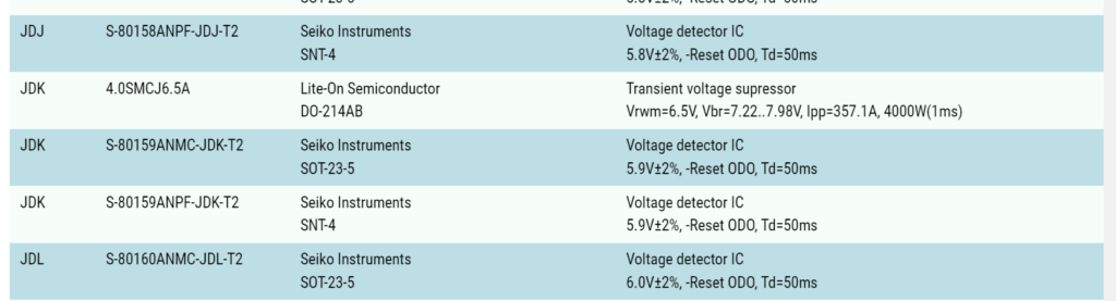
Well … no luck here, it is certainly not a transient voltage suppressor or a voltage detector IC. Then, is there a way to identify it with the specs Pololu gives us ? The U3V40x line has :
- a 2.7V startup voltage
- a minimum 1.3V “hot” operating voltage
- continuous input currents up to 4 A
- 4.5 A for several seconds
- ~600 kHz switching frequency under heavy loads
- 9.5A peak
- 16V maximum input voltage
- efficiency of 90% to 95%
From that I tried looking for a 2.7V min and 1.3V operating voltage. But it isn’t something indexed easily by search engines. What could be a definitive characteristic used to define a unique converter ? Well, its switching frequency and it’s maximum current. The board supports officialy a 4A rating, but I am pretty sure it’s only because of thermal/part rating considerations. Thus, I hypothesized the 9.5A peak rating would be the ic rating. A quick lookup on Google for a “600Khz 9.5A converter” returned as the first result the “MP3437” from monolithicpower. The typical simplified application diagram for the ic is :
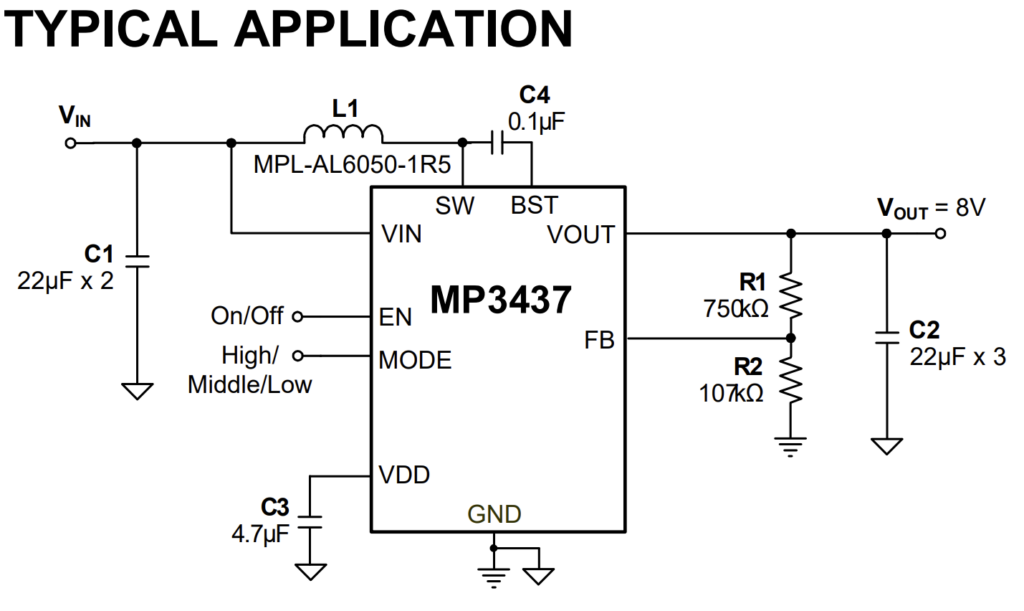
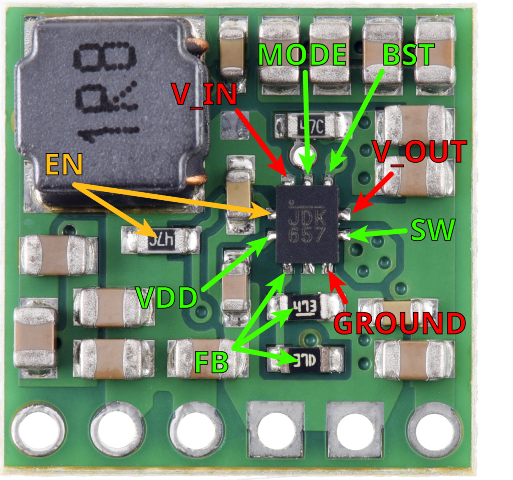
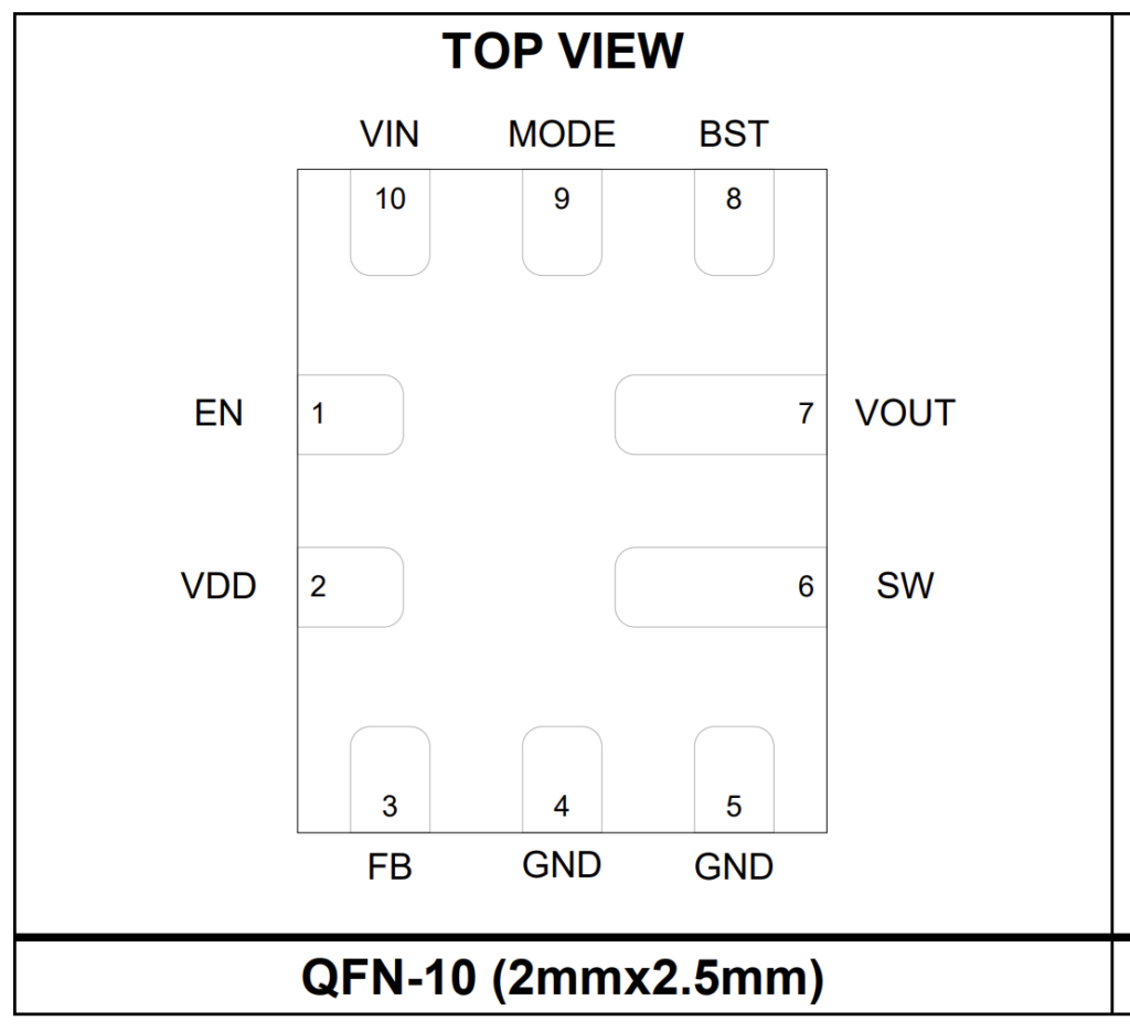
It is a 600kHz, 2.7V startup voltage, 16V maximum, >90% Efficiency, QFN-10 chip… the exact specification I was looking for. Let’s analyze the physical layout. Here is the pinout for the ic, as indicated in the datasheet and as we can analyze from the Pololu board : from the pinout (red), from analyzing the characteristics on Pololu’s site (orange), from the datasheet (green) :
Final verification and outcome
We can easily identify the enable pin with a resistor labeled “47C”, which is a 30100 ohm resistor. It corresponds to the indication of a 30KOhm pull up resistor as indicated by Pololu. Furthermore, the resistor divider for the output voltage selection can be seen at the bottom where the FB (feedback) is located. Finally, the package coincides perfectly with what is on the Pololu boards. It is a QFN-10 package with a 2-3-2-3 pin configuration that seems to match the 2 mm by 2.5 mm. I am almost certain that the regulator used by the Pololu U3V40x family is the monolithicpower’s MP3437 step up converter !
The MP3437 can easily be used in various configurations by adding the right values for the voltage divider. You could even use a variable resistor to adapt a design for multiple uses. If you want to use the boards offered by Pololu the specific boards are :
- U3V40F5 for 5V output
- U3V40F6 for 6V output
- U3V40F7 for 7.5V output
- U3V40F9 for 9V output
- U3V40F12 for 12V output
There is only one thing left to do : design your PCB with this amazing little IC !